The power head test line is applied for testing and automatic adjustment of the Electrical Power Steering System, including inspection on torque, noise, vibration and the control of ECU in simulated running conditions. It is also possible to customize the test line with some other functions. After the workflow, you are able to get complete test reports, and you are allowed to adjust parameters on HMI.
JINLAN insists on design innovation since its foundation in 2007 and implements the standard production flow continuously. All equipment has to be inspected on the performance of trial running before delivery. The data traceability system and information control makes the equipment more intelligent.
Eps Power Head Test Line,Eps Power Head,Eps Power Head Testing Line,Eps Automatic Testing Line Wujiang Jinlan Machinery Manufacture Co.,Ltd , https://www.jinlan-technology.com
The ZSFZ wet alarm valve is a one-way valve that only allows water to flow into the sprinkler system in one direction and drives the associated components to alarm under the specified pressure and flow. The wet automatic sprinkler system consisting of a water flow indicator, a pressure switch and a sprinkler is a widely used fixed fire extinguishing system. The clean water of the system's pipe network, which is filled with constant pressure for a long period of time, has long been in service. When a fire occurs in a certain area of ​​the protected area, the ambient temperature in the area rises, and the organic solution in the heat sensitive element (glass ball) of the sprinkler head Thermal expansion occurs and a large internal pressure occurs until the glass bulb crushes, thereby opening the nozzle to spray water, and automatically start the entire system, emitting an audible and visual alarm signal to achieve the purpose of fire alarm, fire control and fire extinguishing.
ZSFZ type wet alarm valve device is suitable for places with ambient temperature of 4 °C ~ 70 °C. Usually installed in hotels, shopping malls, hospitals, cinemas, office buildings, high-rise buildings, warehouses, and underground garages where there is a risk of fire. For fire sprinkler system design, construction, supervision, please press GB50084-2001 (2005) The provisions of the "Specifications for the Design of Automatic Sprinkler Systems" are implemented.
Product Standard: GB5135·2-2003 "Automatic Sprinkler System Part 2: Wet Alarm Valve, Retarder, Hydraulic Alarm"
2, product structure and working principle Product structure diagram (Figure 1) 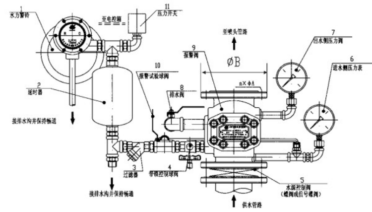
2.1. Structure of the product As can be seen from Figure 1, the ZSFZ wet alarm valve device consists of a wet alarm valve, retarder, hydraulic bell, pressure switch, drain valve, and filter.
2.1.1 Wet Alarm Valve This wet alarm valve is a cover type alarm valve. It is mainly composed of a valve body, a seat ring and a valve flap. The entire valve body is divided into upper and lower chambers by a valve flap, and the upper chamber (system side ) Connected to the system pipe network, the lower chamber (water supply side) communicates with the water source, and there is a seat ring in the valve body. On the seat ring, there are a plurality of groove holes leading to the inlet pipe of the retarder.
When the system is in a servo state, the grooved hole in the seat ring is closed by the valve flap, and the alarm water channel leading to the hydraulic alarm is blocked; when the pressure difference between the upper and lower reaches a certain value, the valve flap is opened ( Differential pressure start), water flows from the water supply side to the system side, the alarm alarm, the water discharge system spray water; when the upper and lower pressure is frequently opened, there is a small make-up valve on the valve flap, when the system side pipe network has small leakage When the pressure of the leakage or water source fluctuates, the water can be supplied to the pipe network through the replenishing valve to balance the pressure in the upper and lower chambers and stabilize the valve flap, thus avoiding false alarms.
2.1.2. Retarder The retarder is a cylindrical water container with an inlet and outlet. The lower end has an inlet and communicates with the alarm port of the alarm valve. The upper outlet is connected to the water alarm. Due to the fluctuation phenomenon of the system's water supply pressure, the valve flap can open instantaneously. Water flows through the grooves and holes in the seat ring and enters the retarder first. Since the time of the water pressure fluctuation is very short, the valve flap can be automatically reset quickly. (Off), so the amount of water entering the retarder is very small, and the water can be collected by the retarder and drained through the drain at the bottom. This buffer time of the retarder acts to avoid the error of the hydraulic bell caused by the fluctuation of the flow pressure. Call the police. The time required for the water to flow from the water inlet of the retarder to the outlet is the delay time. The device is 5~90S. After the water flow is stopped, the water left in the retarder is discharged from the drain, and the required time for draining (drainage time) ) Less than 5min.
2.1.3. Hydraulic Bell The hydraulic bell is a hydraulically driven mechanical device. It is composed of shell, impeller, bell hammer and bell cover. When the valve flap is opened, water flows through the grooves and holes in the seat ring into the retarder. After it is full, it continues to flow into the water inlet of the hydraulic bell. Under a certain flow pressure, the impeller is driven to rotate the bell hammer arm so that The bell hammer hits the aluminum bell continuously and the alarm bell sounds.
2.2. Working principle The wet alarm valve device is in a state of waiting for a long time. The system is filled with working pressure water. When a fire occurs in the control area of ​​the automatic sprinkler system, the heat sensitive component in the closed sprinkler head of the system pipe network is heated and blasted automatically. Water spray, the pressure of the wet alarm valve system drops, under the effect of pressure difference, the valve flap is automatically opened, and the water on the water supply side flows into the system side to infuse water to the pipe network, and the entire pipe network is in an automatic sprinkler state. At the same time, a small amount of water flows through the holes in the seat ring to the retarder and the hydraulic bell. Under certain pressure and flow conditions, the hydraulic bell sounds an alarm and the pressure switch converts the pressure signal into an electric signal to activate the fire pump. The auxiliary fire extinguishing equipment is used for hydrating, and the pipe network equipped with the flow indicator is also operated to output electrical signals so that the system control terminal can promptly discover the area where the fire occurs and achieve the purpose of automatic sprinkler and alarm.
3, installation and commissioning 3.1, installation 3.1.1, wet alarm valve should be installed before the leak test, the test pressure is 2 times the rated working pressure, packing pressure more than 5min, the valve flap should be no leakage;
3.1.2. The device shall be vertically installed on the pipelines for pressure test and flushing. Pay attention to the direction of water flow. The installation position shall consider sufficient space for operation during maintenance and service.
3.1.3 The system piping shall be thoroughly flushed, and the pipe shall be coated with a rust-proof layer to ensure that there is no dirt in the pipeline;
3.1.4. Each drainage outlet application pipeline shall be separately connected to the sewer, so as to maintain unimpededness and facilitate uniform drainage;
3.1.5, the pressure gauge should be turned to see the position of the reading;
3.1.6. Location of hydraulic alarm bell and alarm valve. The connected pipeline is ready to be installed at the factory. If the pipeline needs to be re-arranged, the horizontal distance is ≤ 20m and the height difference is ≤ 5m.
3.2.1 After the pipe network system is installed, fill the system pipe with water, slowly raise the pressure and drain the air in the pipe, raise the pressure to the working pressure of the system, check whether the whole system has leakage, and then pass the test. Alarm test and pipeline water supply test.
3.2.2. Alarm test: Open the end test valve (installed at the end of the system). The hydraulic alarm, pressure switch and water flow indicator should be used for corresponding alarm action. Or open the drain ball valve (8) on the wet alarm valve device. When the flow rate is equivalent to a standard nozzle (diameter is 15mm, flow coefficient K=80±4), the hydraulic bell and pressure switch should make corresponding alarm action. .
3.2.3. Open the alarm test ball valve (10). The incoming water flow from the copper pipe directly into the alarm device. In the case that the valve plate does not open the servo state, it can also test the pressure switch and the water alarm alarm performance test.
4.2.4, pipeline water supply test: open the drainage ball valve (8), there should be a large amount of water flows out stably, indicating that the pipeline water supply is smooth and normal, otherwise it should be checked: the pipeline system exhaust clear plug to ensure unblocked.
4, regular inspections and maintenance 4.1, rubber valve sealing surface, should remove the attached dirt and foreign bodies in a timely manner, rubber seal life is generally within 18 months, if worn, aging, should be replaced.
4.2, the valve seat ring ring groove in the small hole and the sealing surface, foreign matter should be removed dirt, the sealing surface should not be scratched, small holes remain open, can not be repaired should be replaced.
4.3. Clean up the dirt in the filter on the alarm valve device in time to keep the pipeline open.
4.4. Check and clean the dirt inside the retarder. The orifice should not be blocked by foreign matter.
1, explain: