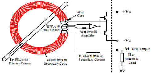
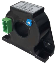
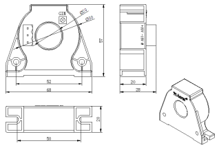
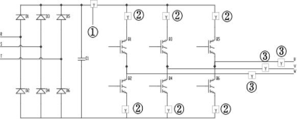
Ankerui Qingqing Jiangsu Ankerui Electric Appliance Manufacturing Co., Ltd., Jiangyin, Jiangsu 214405, China Abstract: This article analyzes the working principle of the closed-loop Hall current sensor and the characteristics and selection of chan products in the industry, and discusses its typical application in frequency converters. Keywords: closed-loop Hall current sensor Operating principle Frequency converter Application 1 Introduction With the continuous deepening of economic reforms, energy conservation and consumption reduction have become one of the important means to reduce production costs and improve product quality, and frequency conversion speed regulation technology is in line with the requirements of industrial production automation development, creating a new era of intelligent motors. . At present, the technology has been practically applied in the motor drive equipment of various industries such as electric power, metallurgy, chemical industry, papermaking, food, textile, etc. It has become a major development direction of modern electric drive technology. Using the inverter to control the motor to realize speed regulation can save more than 10% of electric energy. Due to its excellent characteristics, Hall current transducers are being selected by more and more inverter manufacturers as power monitoring components. 2. How it works The Hall current sensor is a magnetic field sensor manufactured based on the Hall effect. It has two modes of operation, namely open loop (direct) and closed loop (magnetic balance). The advantage of the direct-type Hall sensor is that the circuit is simple in form and relatively low in cost; its disadvantages are poor accuracy, linearity, slow response time, and large temperature drift. In order to overcome its shortcomings, closed loop (magnetic balance) Hall current sensors have emerged. Closed-loop Hall current sensor, also known as zero-flux Hall current sensor, as shown in Figure 1, it is from the primary circuit, magnetic ring, Hall element secondary coil, amplifier and other components. When the magnetic flux generated by the primary current IPchan is concentrated in the magnetic circuit through the high-quality magnetic core, the Hall element is fixed in the air gap to detect the magnetic flux, and the reverse compensation current is output through the multi-turn coil wound on the magnetic core. In order to offset the magnetic flux generated by the primary IP, the magnetic flux in the magnetic circuit is always kept at zero. After special circuit processing, the output of the sensor can output current changes that accurately reflect the primary current. figure 1 3. Product introduction 3.1 product selection The closed-loop Hall current sensor has many advantages such as short response time, high operating frequency, strong overload capability, and high isolation. In general, the Hall current sensor is selected based on the input signal, outline, and bore size. In the sensor industry, Jiangsu Anke Rui Hall current sensors strictly in accordance with the requirements of the JB/T 7490-2007 "Hall current transformer industry standards" requirements, compared to peers using different pin-type wiring, all green Plug terminal, convenient and reliable field wiring. Common brand products are shown in Table 1. Table 1 Common brands model Accuracy Auxiliary power Wiring Ankerui, Jiangsu AHBC series Level 0.5 ±15V Green plug terminal Swiss LEM LA series Level 0.5 ±15V Pin method 3.2 product shape Model: AHBC-LTA Physical map Dimensional drawing 3.3 Technical Specifications l Response time: ≤1us l Bandwidth: 100kHz l Offset current: 0.1mA l Working temperature: -25~70°C l Storage temperature: -40~80°C l Output load: according to different auxiliary power, input signal, output signal l Input overload capacity: Input the maximum range of 2 times to restore normal operation l Withstand voltage: 3.5kV/50Hz/1min 4. Application 4.1 Sensor Applications in Frequency Control Circuits Fig. 2 Frequency conversion speed control circuit Y is Hall current sensor Ø In Figure 2, 1 is used to detect the DC current of the bus. When abnormal pulse occurs in the main loop, or the effective value exceeds the standard, the trigger pulse of the inverter trigger circuit is quickly cut off to protect the inverter and the rectifier module; Ø In Figure 2, 2 is used to detect the current difference between the two arms. Because of the commutation failure, it is easy to damage the IBGT module in the upper and lower arms of a phase due to overcurrent. Short-circuit current protection is required for short-circuit detection at this time. Within 10μs after exit, the gate drive circuit is cut off. This inverter must use fast over-current protection device. Hall current sensor can be used to detect the current in each bridge arm. If the upper and lower arms are conductive at the same time due to the failure of commutation, then The corresponding two sensors detect the current signal at the same time. After being converted into a square wave by comparison with the reference voltage, all the inverter trigger pulses are controlled by the gate circuit to cut off the short circuit and protect the expensive IBGT module. Ø In Figure 2, 3 is used to detect the waveform of the output current, and it is connected to the output circuit of the inverter. It is used to detect the alternating current that changes with the frequency, which can better control the trigger pulse, and can also provide the overload signal of the electrical equipment. 4.2 Usage Notes 1, in order to get better dynamic characteristics and sensitivity, we must pay attention to the primary coil and the secondary coil coupling, to be coupled well, it is best to use a single wire and the wire completely fills the Hall sensor module aperture; 2, when the use of large DC current flowing through the sensor primary coil, and the secondary circuit is not connected to the power | regulator or secondary side open circuit, then the magnetic circuit is magnetized, resulting in remanence, affecting the measurement accuracy (So When using, please turn on the power supply and measurement terminal M). When this happens, demagnetization must be performed first. The method is that the secondary circuit does not add power, but in the primary coil passes the same level of alternating current and gradually reduces its value; 3. In most cases, Hall sensors have strong resistance to external magnetic field interference. Generally, there is a current twice the working current Ip between the distance module 5-10cm. The magnetic field interference generated by the sensor is negligible. However, when there is a stronger magnetic field interference, appropriate measures must be taken to solve it. The usual methods are: 1 Adjust the direction of the module to minimize the influence of the external magnetic field on the module; 2 Put a metal shield against the magnetic field on the module; 3 Select modules with dual Hall elements or multiple Hall elements; 4 The optimal accuracy of the measurement is obtained under the rated value. When the measured current is much lower than the rated value, the best accuracy can be obtained. The primary side can use multiple turns, that is, IpNp=rated ampere turns. In addition, the temperature of the primary feeder should not exceed 80°C. 5. Conclusion Due to its numerous advantages, the Hall current sensor ensures accurate and reliable operation of the inverter through accurate detection and control of large currents, enabling the inverter to process abnormal conditions in a timely manner while properly outputting. It improves the reliability of the inverter and improves the safety of the inverter. Therefore, the advantage of the Hall current sensor in the inverter becomes more and more obvious, and it has become an indispensable part of the inverter industry. LED Strobe Beacon,Warning Beacon Light,LED Emergency Strobe Beacon,Safety Strobe Beacon Shaoxing Groupstar Electric Appliance Co., Ltd. , https://www.led-auto-lamps.com