Motor Cycle Parts,Aluminum Sand Casting,Sand Casting Krong International Trade Limited , http://www.shdiecasting.com
Coordinated control system is mainly composed of the unit power command operation loop, boiler fuel command operation loop, steam turbine door opening command operation loop, etc. to form the main control system.
1 main control system 1.1 unit power instruction computing circuit, as shown in Figure 1.
The load instructions of the power instruction calculation circuit of the unit come from three aspects.
a. The crew operation personnel give a “manual†instruction. This signal expresses the crew’s duty to the unit’s output.
b. Instructions from the Grid Center Dispatch Facility (ADS), which expresses the requirements imposed on the unit's output from the perspective of the distribution of the economic load on the entire grid.
c. Load instructions generated by the "frequency deviation" of the grid, which expresses the energy balance of the entire power grid.
After the above three load instructions are operated by the logic module, the output is the unit power command. Before this instruction was sent out, the unit tracking capability was also used to correct the upper and lower limits of the unit power command and the rate of change, depending on the operation of the unit equipment. 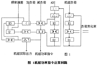
a. The crew watchman “manually†gives the load instruction. The crew watchman passes through the given load instruction in a step-like form. The step value is given exactly as required. This variation will be applied when the adjustment range exceeds a certain range. It is not allowed to exceed the level that the crew can accept. In order to change the unit load according to the speed that the scheduled unit can accept, this step gives the power command and should be linearized by the loop shown in Figure 1.
The output of the “manual†given load instruction is compared with the output signal from the integral module S1 in the comparison module Δ1, and the output deviation signal is amplified by the proportional module K1 and passed through the limit module to the integral module. The output of its integral module is a linearized manual given load command.
It is described as follows: When the flight attendant manually changes the load instruction step by ΔV, the integral component S1 will output: 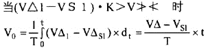
Strictly speaking, the output V0 of the integration module S1 gradually increases, and the output of the comparison module 1 gradually decreases. 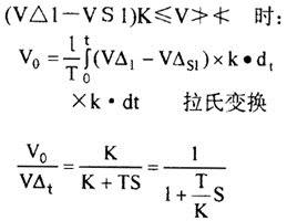
If the manual duty command of the flight attendant is not changed, the step load command dispatched by the center will be divided into two △2 points by the addition module ∑1 and the comparison module, all the way through the change speed limit loop, and the V01 signal will be output by the integrator module S2: Another way to get a signal with the initial step value after limiting the module, after adding V02 to V01 at φ2, the response curve is shown in Fig.3. 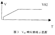
The power change speed limit circuit is completed by the comparison module Δ2, the proportional module K2, the limit module and the integral module S2. The process is exactly the same as the manual duty of the crew on duty.
The output of the integration module S2 is fed back to the comparison module by one step Δ2 and compared with the command from the addition module ∑1. When the two are not equal, the output of the comparison module Δ2 will change the unit power command. When the two are equal, the output of the comparison module Δ2 is zero, so the step change of the same output is also zero, the speed change loop The output, that is, the input module V01 of the integral module is unchanged, equal to the load command from the additive module ∑l, and the input of the load module will ultimately reflect the unit load command.
b. The frequency deviation signal is sent to the low value selection module (2) compared with the unit affluence capability from the comparison module △3. As long as the actual output of the unit is greater than the unit power command, the frequency deviation load command passes through the low selection module (2 and limit The module is sent to the addition module ∑2.
On the contrary, when the actual output of the unit may be less than the power command of the unit, the frequency deviation signal cannot pass through the low selection module, ie, the unit does not participate in grid frequency regulation.
To sum up, the unit power command calculation loop, after the operator's manual command, mid-load command and frequency deviation signal are calculated, it becomes the power command that the unit can accept, and is sent by the addition module ∑2 to control Steam turbine and boiler control loop.
1.2 Steam Turbine Adjustment Commands The arithmetic loop power command is sent to the calculation loop of the turbine speed control door opening command (the DEH regulation control system for daily use meters) and the boiler combustion command in parallel after the addition module ∑2 is formed. Computation loop. Then the turbine speed control door opening instruction and the boiler combustion rate instruction are issued to control the turbine regulation system and the boiler regulation system, respectively, to realize coordinated control of the engine, furnace and electricity. 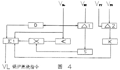
1.3 Boiler Combustion Rate Command Computation Loop Power Deviation (VNO--VNE) The integral gain varies with the power command. The VX output signal of multiplication module X1 is: ![]()
T-integration module integration time.
In the circuit for changing the integral gain, the function of the low limit module ≮ is that when the load command VN0 is less than a certain value VNmin, the load deviation integral signal sent to the addition module ∑1 is: 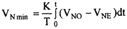
![]()

The output of the additive module ∑1 is the boiler combustion rate command and consists of the following signals:
. Unit power command VNO
. The unit power command passes the differential signal of the VNO differentiation module D.
The differential gain of the KD--differential component in the formula;
TD - The time constant of the differential component. 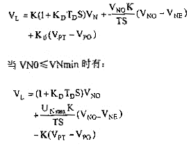
From the above, it can be seen that the power command is the front VN0 feed signal, and the purpose of adding its differential signal is to strengthen the regulation of the boiler combustion rate when the power requirement changes VN0 in order to reduce the influence of the thermal inertia of the boiler. The power deviation signal corrects the combustion rate of the boiler so as to ensure that the actual power of the unit generating unit is equal to the load demand NE vapor pressure deviation signal and that the final VN can be adapted to the combustion string of the steam reformed boiler, for example, when VPT>VP0, The combustion rate is appropriately increased to make up for the decrease in boiler energy storage due to the low pressure. Combustion tracking and "manual" switching are simply the same route, and no analysis is done here.
2 Advanced Control Strategy Currently. Coordinated control of many power plants uses the P1XPS/PT; P1 X CXdP/dt mathematical model. This is the DirectEnergyBalance control mode. See (5) below: 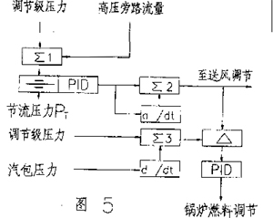
Among them: P1: Steam turbine first stage pressure; PT: Throttle pressure; PS: Throttle pressure setting value: dP/dt: Drum pressure change rate.
The PI/PT ratio energy balance signal on the left side of the program represents the linear opening of the actual main valve, and the entire signal is not affected by the boiler internal disturbance. When multiplied by PS, (P1/PT)*PS represents the boiler energy signal (which may represent the control boiler input command signal), ie: P1XPS/PT = boiler energy command, regardless of the status of the turbine in manual, automatic, frequency modulation, etc. The balanced signals all represent the boiler's need for boiler input (wind, fuel). The energy balance signal is automatically calibrated because P1 is usually fed back to the turbine control, so the turbine controller will control the main valve to adapt to the power change requirements. P1 Directly proportional to the energy signal input to the turbine, since the boiler's energy storage can respond quickly, the power generation can respond quickly. When the coal transportation system and the combustion process lag, the main steam pressure PT will fall, the boiler energy command will increase, and the boiler will burn excessively to supplement the lost energy storage. When the pressure returns to the fixed point, the boiler command will decrease. , return to normal. The PI+CXdP/dt on the right side of the equation is a heat signal, which can also represent the feedback signal of the fuel quantity. Because this heat signal takes into account changes in the pressure of the drum, it represents the balance between the input and output of the boiler. When the boiler is in steady state, The drum pressure does not change (dp/dt = 0) and the fuel input equals the boiler output.
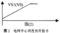
At present, the control of large unit units adopts coordinated control. In the design of the coordinated control system, the main considerations are the stability and disturbance in the regulation. The basic idea is to adjust the control system design to a coarse adjustment with the disturbance amount, and to adjust the feedback control system with a feedforward feedback with fine tuning. . The main task is to coordinate the machine, furnace, and electricity of the unit units to balance the coordinated dynamic control of wind, coal, water, and electrical loads to accommodate external load requirements while ensuring the unit's safety and economical stability. . The following are described separately: According to the above equation, when the integral time T is constant, the magnitude of the V0 change speed is determined by the limiting value of the amplitude limiting module. In this way we can "manually" determine the rate of change of a given load instruction. This is the first-order inertia link. However, since the value of K is large, the last non-periodic process is very short, ie the integrator module can be considered as being linear to a given reproduction. as shown in picture 2. The power grid center dispatches the load instruction that sends the unit to increase or decrease the load as a step signal. The crew is required to meet its requirements as soon as possible. However, if the step signal is too large, if the load variation of the unit is exceeded, it will be detrimental to the safe operation of the unit. Therefore, the output of the addition module ∑1 should also be processed so that the processed load command has an initial step change acceptable to the unit and then changed at a certain speed. The step load limitation and speed limit calculation are performed on the load command output from the addition module ∑1. The load reduction is achieved by limiting the module v11v≯≮ and adding the load by selecting a module with a small value (the minimum value is the step limit value when the load is added). The output of the limiting module in the unit may actually exceed the capacity of the unit in the unit When the power command is above X%, the output value is X%: When the difference between the actual output of the unit and the power command of the unit is less than X%, the actual difference is output. Where: the coefficient of the K-multiplication module X1. After the coefficient of the proportional module is VN0>VNmin, the combustion rate command is as follows: In the formula, the coefficient of the K proportional module is: When VN0>VNmin, the combustion rate command is as follows: As shown in Figure (4), its working principle is: