Flow meter installation 1. Thoroughly clean the pipeline before installation and install a filter in front of the flowmeter to prevent debris from entering the flowmeter. When the liquid to be measured contains gas, an air separator should be installed. 2. It should be noted that the oval gear shaft of the flowmeter must be placed in a horizontal position, ie the dial is perpendicular to the ground plane. Adjust the flow and start, closed valves should be installed in the inlet and outlet ends of the flowmeter. 3. The arrow on the flowmeter housing should point in the same direction as the flow of the liquid to be installed. 4. In the pipeline of continuous process, the horizontal pipeline for installing the flowmeter shall be equipped with a bypass valve for regular cleaning and overhaul. Flowmeters on vertical pipes should be installed in the bypass pipe to prevent debris from falling into the meter. 5 , in the correct installation of the meter under the conditions, for ease of reading, according to the need to rotate the counter 180o or 90o installation requirements shown in Figure 3 Second, the use of matters needing attention: 1. Never test the flowmeter with water. 2. When starting or stopping, open and close the valve should be slow to prevent sudden impact, and should prevent backflow. 3. When the flowmeter is inspected and repaired, the rear cover must not be disassembled, so as to avoid any change in precision when reloading and affect the accuracy. X. Error Calculation and Adjustment (1) The basic error of the flowmeter is determined by the following measured values ​​for each test flow point: (volumetric method) E=Vm - V/V × 100 % E - flow meter error (generally refers to cumulative error) to take two significant figures. Vm - Measured value of flow meter (ie indication) V - After correction, the value measured by the flowmeter's standard device (ie actual value) is calculated from the basic error formula. When Vm > V , the basic error of the flowmeter is a "+" value, indicating that the flowmeter is moving faster. When Vm < V , the basic error of the flowmeter is a "-" value, indicating that the flowmeter is slow. In order to make the flowmeter error within the basic error limit, errors often need to be made. That is, by changing the pair of adjusting gears (adjusting teeth) installed in the counter to change the mechanical transmission speed ratio, the flow meter display value is adjusted. The error adjustment cannot change the flow characteristics of the flowmeter and its characteristic curve is artificially in the new coordinate system. Generally speaking, the basic error range of the maximum and minimum flow verification points is not greater than the basic error limit of the specified accuracy within the specified (or actually used) flow range, and the basic error of the flowmeter can be qualified through error adjustment. Flowmeters that have already been used generally use the original adjustment gear set for error checking, and then perform error adjustments based on the specific error conditions. Working principle and structure:
Naipu ISW end suction pumps designed in accordance with ISO2858 standard,are single-stage single-suction horizontal centrifugal pumps featured by integrated simple construction for less space, easy installation, smooth operation with less noise and free of daily maintenance due to the introduction of high quality mechanical seals and closed coupling.
Typical Applications---
Various kinds of industrial application
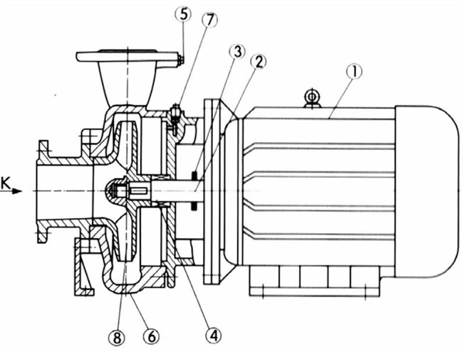
ISW End Suction Pump Configuration Drawing
Main Part Number At The Drawing
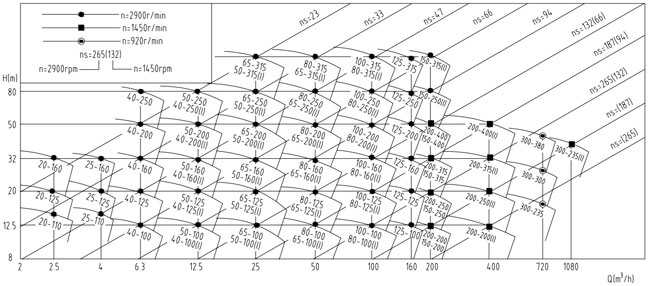
ISW END SUCTION PUMP SELECTION CHART
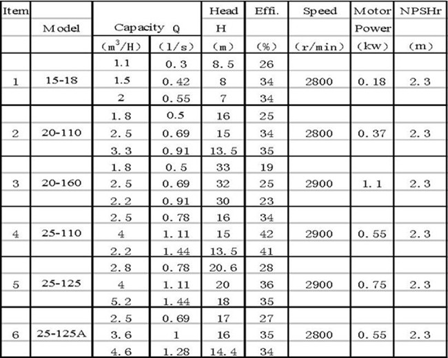
NP- ISW END SUCTION PUMP PERFORMANCE PARAMETERS
ISW End Suction Pump,End Suction Pump,Clear Water Pump,End Suction Water Pump Shijiazhuang Naipu Pump Co., Ltd. , https://www.naipu-pump.com
The flow meter consists of a metering box and a pair of oval gears mounted in the metering box. The upper and lower cover plates form a sealed primary lunar cavity (which is not absolutely sealed due to the rotation of the gears) as a unit of calculating the primary displacement. When the liquid to be measured enters the flowmeter through the pipeline, the pair of gears are continuously rotated due to the pressure difference between the inlet and outlet, and the liquid measured by the initial cavity is continuously conveyed to the outlet. The number of rotations of the oval gear and each The product of four times the secondary displacement is the total amount of measured fluid flow
Water supply system
Lowering underground water level
Boosting
Gardening and aricultural irrigation

2 Shaft
3 Deflector
4 Mechanical Sea
6 Pump Casing
7 Pressure Release Plug
8 Impeller


1 Motor
5 Pressure Monitoring Hole